Building IoT Microservices with the Micronaut® Framework
By Chip Jones, OCI Partner and Principal Software Engineer
February 2022
Introduction
Current IoT development trends focus on hybrid solutions that deploy IoT capabilities to both the cloud and to the edge where IoT devices live. In this article we explore an efficient technique for developing components that can be deployed to edge computing devices. We use a Raspberry Pi as the computing platform, since it is very low cost and relatively easy to configure, and we leverage the open source Micronaut® framework as a tool to simplify the development effort.
The Micronaut framework is a JVM-based software solution that supports the development of microservices and can be deployed to computing environments that don't require extensive compute or memory footprints. Micronaut uses an innovative approach to compile-time optimizations to achieve runtime efficiencies that enable Micronaut-based applications to perform very well on edge computing devices, which often have limited computing resources available.
In this article, we describe a complete IoT application deployed on a Raspberry Pi that monitors light levels and controls an LED. The purpose is to explore how to build an IoT application for edge computing devices with sensors and actuators, rather than to focus on the specific functionality. This initial capability can be used as a springboard for more complex IoT solutions devoted to specific environmental monitoring and control applications.
Background
Raspberry Pi
Raspberry Pi is a general purpose single-board computer (SBC) developed by the Raspberry Pi Foundation. Raspberry Pi is a trademark of Raspberry Pi Trading. These ARM-compatible devices run a variety of operating systems, including the Debian-based Raspberry Pi OS, Ubuntu Linux, and Windows 10 IoT. The low-cost computers are widely used in education, in industry, and by hobbyists.
Most versions of the Raspberry Pi support USB, HDMI, Bluetooth, and Wi-Fi. In addition, the devices have either 26 or 40 general purpose input-output (GPIO) pins. These programmable digital I/O connectors support a variety of protocols, including I2C and SPI, making the devices an effective prototyping tool for IoT applications.
Micronaut Framework
The Micronaut framework is a modern full-stack toolkit backed by the Micronaut Foundation™. This microservice Framework is designed for building modular, easily testable microservice applications. The Micronaut framework utilizes innovative techniques at compile time to preconfigure much of the application's initialization logic, dramatically decreasing startup time and runtime memory requirements. This is one of the reasons that Micronaut services can be a great fit for edge devices with constrained environments.
The Micronaut framework was developed by the creators of the Grails® framework and takes inspiration from lessons learned over the years building real-world applications from monoliths to microservices using Spring, Spring Boot, and the Grails framework.
The Micronaut framework aims to provide all the tools necessary to build full-featured microservice applications, including:
- Dependency injection (DI) and inversion of control (IoC)
- Sensible defaults and auto-configuration
- Configuration and configuration sharing
- Service discovery
- HTTP routing
- HTTP client with client-side load-balancing
At the same time, the Framework aims to avoid the downsides of frameworks like Spring, Spring Boot, and Grails by providing:
- Fast startup time
- Reduced memory footprint
- Minimal use of reflection
- Minimal use of runtime proxies
- Easy testing
Historically, frameworks such as Spring and Grails were not designed to run in scenarios such as serverless functions, Android apps, or low memory footprint microservices. In contrast, the Micronaut framework is designed to be suitable for all of these scenarios.
This goal is achieved through the use of Java’s annotation processors, which are usable on any JVM language that supports them, as well as an HTTP Server and Client built on Netty. In order to provide a similar programming model to Spring and Grails, these annotation processors precompile the necessary metadata in order to perform DI, define aspect-oriented programming (AOP) proxies, and configure your application to run in a microservices environment.
Many of the Micronaut APIs are heavily inspired by the Spring and Grails frameworks. This is by design and aids in bringing developers up to speed quickly.
A Micronaut-based Light Sensing Circuit
Our example uses the Micronaut framework and Pi4J v2 to interact with circuits connected to the Raspberry Pi’s IO pins. The microservice application controls an LED and measures the resistance of a photoresistor, also called an light-dependent resistor (LDR).
The resistance of the LDR is higher when the room is darker. It’s an analog component, so we can’t measure the resistance directly with the Raspberry Pi’s digital GPIO pins. Instead we add a capacitor to the circuit and let the Raspberry Pi measure the time it takes to charge the capacitor. When the room is dark, the LDR has a higher resistance, and the charge time is longer. If the charge time is above a configurable threshold, the application turns on the LED. This lets the Raspberry Pi act as a simple night light.
The example was tested on Raspberry Pi 3s with version 11 of the Raspberry Pi OS (based on Debian “bullseye”).
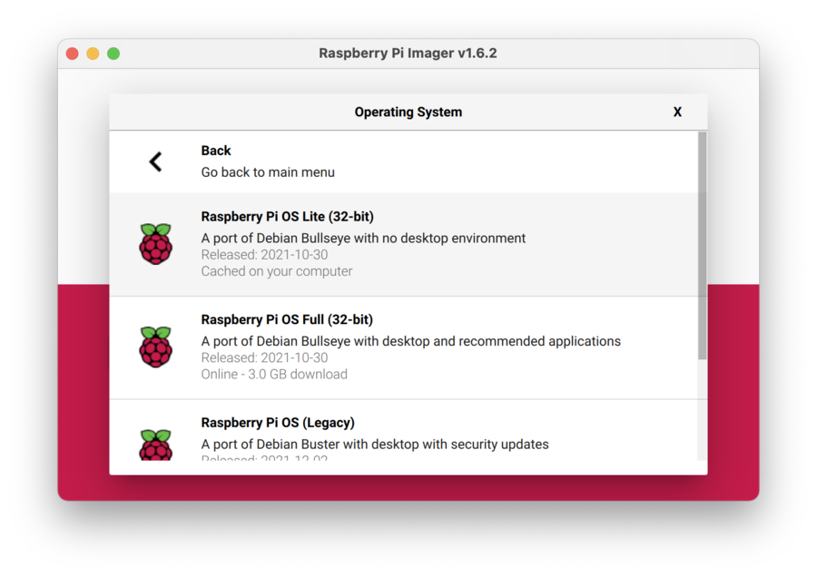
Creating The OS Image
The Raspberry Pi Imager provides the simplest way to install Raspberry Pi OS to an SD card. It is recommended that you choose the Raspberry Pi OS Lite (32-bit) image as a starting point, unless you need the desktop environment and additional applications included in the full image.
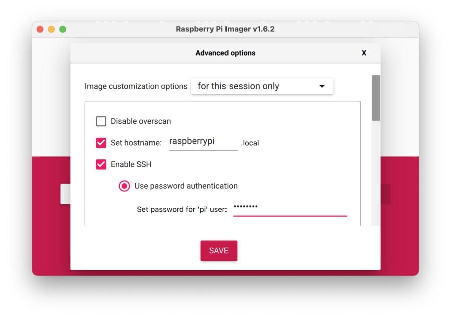
Before writing the image:
- Initiate the Advanced Options interface by pressing CTRL+SHIFT+X.
From the Advanced Options:
- Enable ssh
- Provide a password for the pi user,
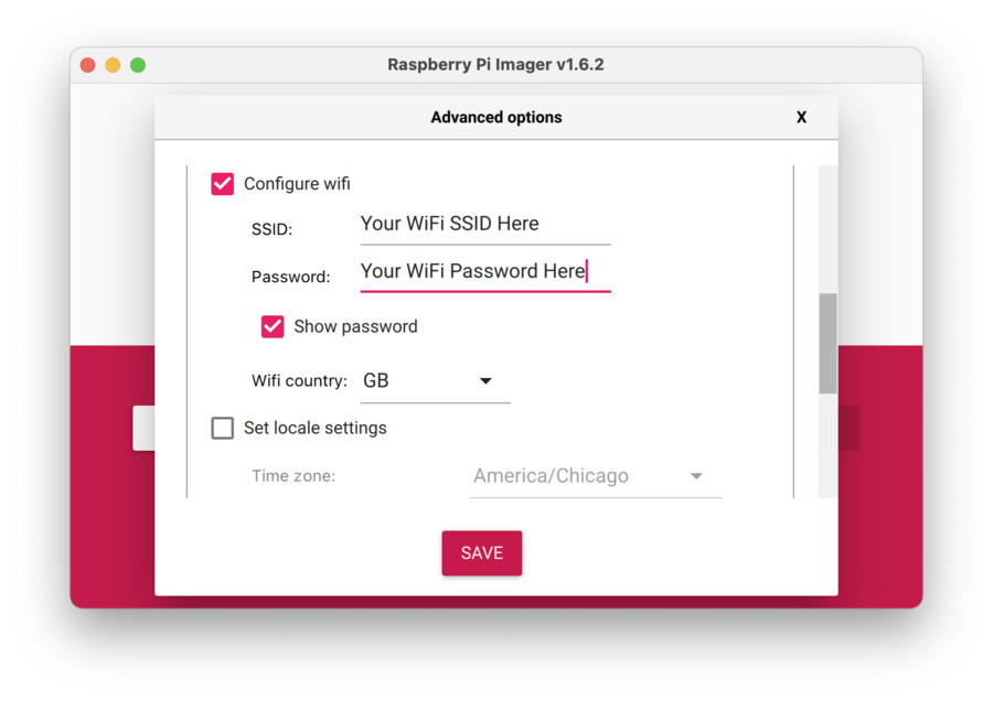
- Configure Wi-Fi so the device will connect to your local network on startup
Optionally, you can provide a custom hostname. The default hostname is raspberrypi.local.
With those settings in place, along with selecting which storage device (the SD Card) you want the image written to, the Imager is ready to write the SD card image.
Once the SD card is prepared, insert it into the Raspberry Pi and power the device up. After a minute or two, the device should:
- Boot and connect to the local network
- Appear on your network under the name specified in the Advanced Options (or
raspberrypi.localif you accepted the default) - Respond to ping requests
- Be listening for ssh connections
Using an ssh client of your choice, ssh to the device using the “pi” username and the password specified in the Advanced Options.
Once logged in to the device, you will need to install some support libraries that the IoT demo requires. Those are most easily installed using apt-get.
sudo apt-get update
sudo apt-get install pigpio default-jdk
All of the sample code has been tested using OpenJDK 11.
Hardware Setup
As previously mentioned, photoresistors are analog devices, but the Raspberry Pi does not directly support analog I/O, so it cannot read a value from the photoresistor. Instead, it measures the time the circuit takes to charge a capacitor connected to the photoresistor.
More complex circuits use analog-to-digital converters to generate a more accurate value that the Raspberry Pi can read.
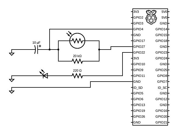
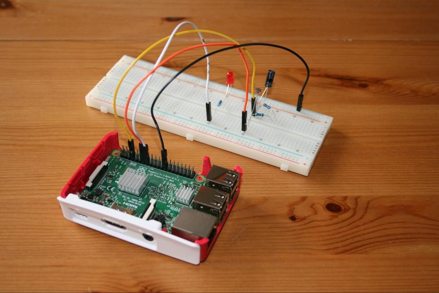
As shown in the photo and diagram above, four of the Raspberry Pi’s GPIO pins connect to the circuit components.
1. GPIO27 connects to one side of the LDR and acts as a trigger that the microservice can set as either high (1) or low (0).
2. GPIO4 is an input pin where the Raspberry Pi measures a voltage. It connects to the other side of the LDR and the positive side of a 10μf polarized capacitor.
3. The negative side of the capacitor connects to ground (Pin 25).
- The circuit has two 10K Ω resistors in series connected to the legs of the LDR, equivalent to a 20K Ω in parallel to the photoresistor as shown in the schematic. This sets an upper bound on the measurement time.
- When GPIO27 is set from low to high, the capacitor charges, and the Raspberry Pi senses a high signal on GPIO4. The reported darkness level is the approximate time it takes to charge the capacitor.
4. GPIO22 connects to the positive (anode) side of an LED. The negative (cathode) side connects to ground. Setting GPIO22 high turns on the LED.
Building and Running
It’s possible to install and build the source directly on a Raspberry Pi, but we recommend building on a Linux, MacOS, or Windows desktop, transferring the .jar file to the Raspberry Pi with scp, and starting the application with an ssh connection.
Download the source code from https://github.com/oci-labs/iot-light-sensor/archive/refs/tags/v1.0.zip or clone from the github repository at https://github.com/oci-labs/iot-light-sensor.
To build the source, navigate to the root directory and build a fat jar that includes all the dependencies the Micronaut application needs.
$ ./gradlew shadowJarCopy the jar file to the Raspberry Pi:
$ scp ./light-sensor/build/libs/light-sensor-1.0-all.jar pi@raspberrypi.local:Connect to the Raspberry Pi with ssh:
$ ssh pi@raspberrypi.local
pi@raspberrypi.local's password:
Linux raspberrypi.local 5.10.63-v7+ #1488 SMP Thu Nov 18 16:14:44 GMT 2021 armv7

pi@raspberrypi.local:~ $
Pi4J depends on the pigpio C library, so you must use the sudo command to launch the application on the Raspberry Pi:
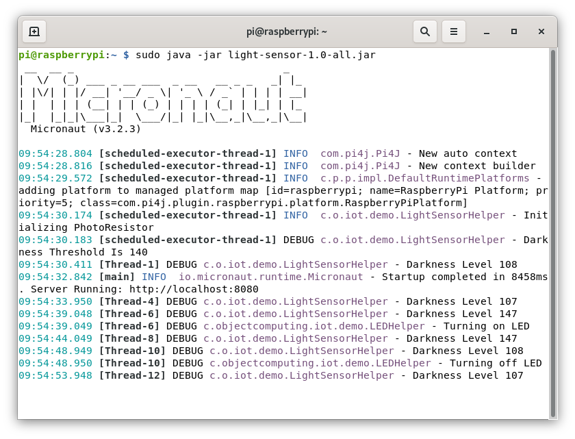
$ sudo java -jar light-sensor-1.0-all.jarIt is possible to interact with the light sensor microservice from a remote machine. Two commands are supported and available via URI endpoints.
Users can query the status ...
$ http raspberrypi.local:8080/light
HTTP/1.1 200 OK
Content-Type: application/json
connection: keep-alive
content-length: 45
date: Mon, 24 Jan 2022 21:38:54 GMT

{
    "time": "24-01-2022 09:38:54 UTC",
    "value": 41
}
... or set a new threshold value for the LED:
$ http POST raspberrypi.local:8080/light/threshold/35
HTTP/1.1 204 No Content
connection: keep-alive
date: Mon, 24 Jan 2022 21:39:04 GMT
The updated threshold value is displayed in the console log on the Raspberry Pi:
20:49:42.777 [Thread-10] DEBUG c.o.iot.demo.LightSensorHelper - Darkness Level 42
20:49:45.755 [default-nioEventLoopGroup-1-2] DEBUG c.o.iot.demo.LightSensorHelper - Darkness Threshold Is 35
20:49:47.776 [Thread-12] DEBUG c.o.iot.demo.LightSensorHelper - Darkness Level 41
20:49:47.777 [Thread-12] DEBUG c.objectcomputing.iot.demo.LEDHelper - Turning on LED
Understanding the Code
Pi4J Configuration
A Gradle build file manages the Pi4J dependencies and packages the required Pi4J files in the Micronaut solution jar file as the Gradle shadowJar task. This is specified in the pi4-utils/build.gradle file.
// pi4j-utils/build.gradle
dependencies {
   api 'com.pi4j:pi4j-core:2.0'
   api 'com.pi4j:pi4j-plugin-raspberrypi:2.0'
   api 'com.pi4j:pi4j-plugin-pigpio:2.0'
}
The Pi4J GPIO configuration logic resides in the pi4j-utils directory.
Pi4J is a third-party library compiled separately from the Micronaut example code, so we use the @Factory annotation to define a factory that creates an instance of Context. That instance will be managed as a bean in the Micronaut application context.
The Pi4JFactory class creates the Pi4JContext bean the application uses to access the GPIO pins.
// Pi4JFactory.java
@Factory
public class Pi4JFactory {
   @Singleton
   @Bean(preDestroy = "shutdown")
   public Context createPi4jContext() {
       return Pi4J.newAutoContext();
   }
The @EachBean annotated methods in the Pi4JFactory direct the Micronaut framework to configure DigitalOutputs or DigitalInputs for each device specified in a config file. These output and input objects become beans in the context and are used by the LED and LightSensorHelper classes to interact with the circuit.
// Pi4JFactory.java
@EachBean(DigitalOutputConfiguration.class)
public DigitalOutput createDigitalOutput(DigitalOutputConfiguration config, Context pi4jContext) {
   var outputConfigBuilder = DigitalOutput.newConfigBuilder(pi4jContext)
           .id(config.getId())
           .name(config.getName())
           .address(config.getAddress())
           .shutdown(config.getShutdown())
           .initial(config.getInitial())
           .provider(config.getProvider());
   return pi4jContext.create(outputConfigBuilder);
}
The createDigitalOutput method expects a DigitalOutputConfiguration object, which is supplied by the Framework.
DigitalOutputConfiguration is a simple class consisting primarily of getters and setters for the several Pi4J configuration options.
// DigitalOutputConfiguration.java
@EachProperty("pi4j.digital-output")
public class DigitalOutputConfiguration {
It is a similar case with createDigitalInput, which expects a DigitalInputConfiguration object.
// Pi4JFactory.java
@EachBean(DigitalInputConfiguration.class)
public DigitalInput createDigitalInput(DigitalInputConfiguration config, Context pi4jContext) {
   var inputConfigBuilder = DigitalInput.newConfigBuilder(pi4jContext)
           .id(config.getId())
           .name(config.getName())
           .address(config.getAddress())
           .debounce(config.getDebounce())
           .pull(config.getPull())
           .provider(config.getProvider());
   return pi4jContext.create(inputConfigBuilder);
}
// DigitalInputConfiguration.java
@EachProperty("pi4j.digital-input")
public class DigitalInputConfiguration {
What's important in the two configuration classes are the @EachProperty annotation and the string arguments "pi4j.digital-output" and "pi4j.digital-input".
@EachProperty directs the Framework to instantiate a DigitalOutputConfiguration for each config item in an application.yml file.
The strings "pi4j.digital-output" and "pi4j.digital-input" tell the Framework how to look up the configuration options within the file (see below).
# light-sensor/src/main/resources/application.yml
pi4j:
 digital-input:
   photo-resistor-input:
     name: Photo Resistor Input
     address: 4
     debounce: 100000
     pull: PULL_DOWN
     provider: pigpio-digital-input
 digital-output:
   led:
     name: LED Output
     address: 22
     shutdown: LOW
     initial: LOW
     provider: pigpio-digital-output
   photo-resistor-output:
     name: Photo Resistor Output
     address: 27
     shutdown: LOW
     initial: HIGH
     provider: pigpio-digital-output
@EachBean and @EachProperty allow us to reconfigure the circuit solely by changing a configuration file without having to modify or recompile code. This is an efficient way to configure a system, and it scales easily, requiring the same number of lines of source code for 1 or 100 devices.
Light Sensor Logic
The light-sensor directory contains device control and application URI endpoint logic. Application endpoints are specified in the file LightSensorController.java. In addition to the @Controller annotation, @Get and @Post annotations configure the /light and /light/threshold URIs respectively.
// LightSensorController.java
@Controller("/light")
public class LightSensorController {

   private final LightSensorHelper sensorHelper;

   public LightSensorController(LightSensorHelper sensorHelper) {
       this.sensorHelper = sensorHelper;
   }

   @Get
   public Darkness status() {
       return sensorHelper.getDarkness();
   }

   @Post("/threshold/{i}")
   public HttpResponse update(@Positive int i) {
       sensorHelper.setDarknessThreshold(i);
       return HttpResponse.noContent();
   }
}
The status() method returns a Darkness object, which encapsulates the darkness level and a timestamp. The class is annotated with @Introspection, which directs the Micronaut framework to generate BeanInfo at compile time in order to avoid runtime reflection.
// Darkness.java
@Introspected
public class Darkness {
   private final int value;
   private final Date time;

   public Darkness(int value) {
       this.value = value;
       time = new Date();
   }

   public int getValue() {
       return value;
   }

   @JsonFormat
           (shape = JsonFormat.Shape.STRING, pattern = "dd-MM-yyyy hh:mm:ss zzz")
   public Date getTime() {
       return time;
   }
}
The LEDHelper class turns the LED on and off.
The @Singleton annotation in LEDHelper.java is all that's required to let the Micronaut framework know to create an instance of LEDHelper at runtime and add it to the context.
LEDHelper's constructor expects a DigitalOutput bean so that it can interact with the physical LED. This bean is managed by the Framework.
// LEDHelper.java
@Singleton
public class LEDHelper {
   private static final Logger log = LoggerFactory.getLogger(LEDHelper.class);

   private final DigitalOutput ledOutput;

   public LEDHelper(@Named("led") DigitalOutput ledOutput) {
       this.ledOutput = ledOutput;
   }

   public void ledOn() {
       if (ledOutput.isLow()) {
           log.debug("Turning on LED");
           ledOutput.high();
       }
   }

   public void ledOff() {
       if (ledOutput.isHigh()) {
           log.debug("Turning off LED");
           ledOutput.low();
       }
   }
}
LightSensorHelper.java contains the logic that times the LDR circuit. Like its LEDHelper class counterpart, it's an @Singleton and gets a DigitalOutput and DigitalInput from the Micronaut context. It attaches an event listener to the input bean, so that code executes upon GPIO4 state changes.
// LightSensorHelper.java
sensorInput.addListener(e -> {
   log.trace("input listener notified");
   if (sensorInput.isHigh()) {
       endTime = System.currentTimeMillis();
       darknessValue = (int) (endTime - startTime);
       log.debug("Darkness Level {}", darknessValue);
       updateLed(darknessValue > darknessThreshold);
   } else {
       startTime = System.currentTimeMillis();
       sensorOutput.high();
   }
   log.trace("INPUT state change: {}", sensorInput.state().toString());
});
Using the @Scheduled annotation, the LightSensorHelper bean will call updateLED() every 5 seconds.
// LightSensorHelper.java
@Scheduled(fixedRate = "5s")
public void updateLED() {
   if (sensorInput.isHigh()) {
       sensorOutput.low();
   }
}
This method sets the sensorOutput to low. The capacitor discharges to a threshold voltage, at which point the sensorInput line (GPIO4) reads low. This causes the sensorInput listener to fire. It records a start time and then sets the sensorOutput (GPIO27) to high. The capacitor then charges, causing the sensorInput (GPIO4) to read high, which fires the listener a second time so that it can record a stop time.
If the amount of time it takes to charge the capacitor is greater than the current threshold, the LED will illuminate; otherwise the LED will not illuminate.
Conclusion
This article described a complete IoT solution for measuring ambient light using a Raspberry Pi and demonstrated several unique features of the Micronaut framework that make it well-suited for IoT development. The purpose was to explore how to build an IoT application for edge computing devices with sensors and actuators, more than to focus on the specific functionality. This demonstration can be used as a springboard for more complex IoT applications.
Acknowledgments
Thanks to Kevin Stanley and Jeff Brown of the Unity Foundation for design and editorial contributions to the article and the project code.
Software Engineering Tech Trends (SETT) is a regular publication featuring emerging trends in software engineering.
